MG-Cars.com
Triumph TR6 Carb rebuild/overhaul BBS discussion at MG-Cars.net

MG-Cars.net
Welcome to our resource for MG Car Information.
Recommendations
Parts
TR parts and Triumph parts, TR bits, Triumph Car Spares and accessories are available for TR2, TR3, TR3A, TR4, TR4A, TR5, TR6, TR7, TR8, Spitfire and Stag and other TR models are available from British car spares and parts company LBCarCo.
Triumph TR6 - Carb rebuild/overhaul
| Guys, I decided to rebuild my carbs myself. Like other stuff about retoring this LBC to it's former (or maybe never had) glory, I end up doing things myself rather than contracting the service or buying new parts. So it is with the Carburettors and after having dissassembled one, I see that it really is not difficult. The TRF rebuild kit that I ordered does not have all the parts I expected particularly the by-pass diaphragam and gaskets, the throttle shaft and throttle shaft seals. My references advise to replace the Throttle Shaft seals and maybe the shaft itself if it's a first rebuild or if the carbs have not been used in some time. Mine have not seen service in at least 23 years so the question has become should I buy the extra parts and fully rebuild the carbs or just settle for what's in the kit (gaskets (float bowl, upper chamber), 0-rings, upper chamber diaphragm, needle and seats). Thanks for your thoughts/comments. One other area...the linkage has several (3, I think) ball joints which are secured by a screw plug held in place by a very small cotter pin. Obviously these joints need a liberal dose of lubrication, but should they also be dissassembled, cleaned and painted or powder coated or am I going a mite too far in tear down?? Anyone done this before? db |
| Doug Baker |
| Doug Do the full thing. I rebuilt my carbs with the standard kit and then tried to tune the car. I couldn't get the idle to stay. It hunted up and down up and down. I went to the refenrences, and determined that it probably was leaking air across the throttle seals . So I had to remove the carbs and install the throttle shaft seals. Like you my carbs had been sitting unused and dry for 20 years and I would guess the seals had turned to hard rubber. Do it once so you don't have to pull them off again. I cleaned and just spray painted my linkages. |
| Michael Petryschuk |
| Don't forget the compensators |
| DON KELLY |
| Hey, Doug. After 23 years I'd play it safe and replace all o-rings and flexible parts. If the carbs are adjustable needle types that includes the o-ring on the adjuster screw unless you want to fill the dashpots frequently. The good news is the the needles may be ok - have to inspect them, though. The throttle shafts may be worn so it may be a good bet to replace those. I wouldn't worry about the bushes, though. Definitely new shaft seals, though. I just oiled up the linkage joints. |
| Brent B |
| "or am I going a mite too far in tear down?? " Are my ears deceiving me???? are my eyes deceiving me???? Doug, don't start cutting corners now....you have done a good job so far. Keep it up. I would go the distance on the carbs also. A little air leak down the road will give you much grief. Rick PS we will be going down I75. |
| Rick Crawford |
| I say clean em ,gut em, and install TBI's in em!! |
| DON KELLY |
| OK, guys, I've finally received my Carb rebuild kits from TRF and as expected they're lacking a whole bunch of stuff. Looks like this kit is for a superficial rebuild, i.e., no provision for the Cold Start, or by-pass valve and nothing for the needle except an O ring. I'll order up the remaining parts, but need some help understanding how to get the damn needle out. I followed the instructions in both the Bently Shop Manual and Nelson Riedel's article, but no luck. The needle DOES NOT just pull out!! I slackened the retaining screw and using a 1/8" allen wrench turned the needle adjusting screw as directed, counter (or anti) clockwise. It turns with some respectable resistance, but nothing else happens. The needle DOES not come out; the needle adjusting screw apparently does not disengage. The slot where the needle retaining screw engages the needle housing DOES NOT move. Should it? I've experimented with the needle retaining screw all the way in and completely removed. No change. What am I doing wrong?? Thanks. db |
| Doug Baker |
| I've run into the stuck needle before and found that if a good long soak in solvent didn't allow it to come out, it was time to resort to more drastic measures. Careful application of heat from a propane or butane torch over a few heat and cool cycles would break up corriosion or gummy deposits and finally allow the needle to be removed, typically while the piston is still hot. Don't be afraid to grab that needle with a small pair of vice grips if you replacing it anyway and give a hard pull. Just remember that if the pistion is still hot to protect your hand from burns. As for the completeness of the kits, they leave alot to be desired but unfortunately that's just the way it is and has been going back to when these cars were new. I guess it was because there were enough different versions of these carbs that a generic kit was supplied and then the specific bits for a given application were obtained outside the kit to help hold the kit numbers to be stocked at a minumum. The alternatives would have been nine zillion different kits to keep on hand. |
| SteveP1 |
| Steve, Thanks for weighing in. I follow your thinking, but wonder if I've really succeeded in separating the needle from the needle adjusting screw. I can pull the needle down to the travel length of the internal spring, but no further; about a 1/4" or so. Is there something that I can do to confirm that the adjusting screw is out? Does the Delrin washer come out with the needle and housing? And if the retaining screw really is spring loaded...I surely lost the spring, cause there ain't one!! Rather than a torch (I'm REALLY leary of that much heat in my untrained hands) how about a bath of hot water to bring the whole thing up to operating Temp of ~190F. Would that be enough to cause the aluminum to expand and the brass not? Thanks. db |
| Doug Baker |
| Oh, just beat the crap out of it Doug. I know you must have some pent up frustration with this car by now! |
| DON KELLY |
| I would use a bath of hot/boiling water before I used a torch on a carb part Doug. Try to keep the needle out of the water and submerge the aluminum only. Hopefully it will be successful and you won't have to go to a torch. |
| Michael Petryschuk |
| Doug, as far as I can remember there is no spring on the needle retaining screw and the only thing that came out was the needle assembly itself. After that, to replace the o-ring seal for the carb damper well you have to drive out the adjuster screw and a star washer that retains it. You may as well plan on ordering a couple of extra star washers as they are rather small and easily lost and the ones that come out are not really suitable for reuse. On the water bath, I don't see why you couldn't try that before resorting to the torch, but would do as Mike suggests since you are relying on differential thermal expansion rates and to some extent selective expansion and contraction to get the bits apart. My primary issue with the water bath approach is that I just don't see it getting hot enough to get you there expansion wise. |
| SteveP1 |
| Mike, Steve, Thanks both for excellent information. Steve, glad to know that I did not lose a spring, although, I felt certain that I "caught" everything that came out with the grub screw. I cannot figure out if the "slot" is supposed to turn w/o the grub screw locking it down. Mine does not. That is the Needle Adjusting screw mechanism "appears" to turn but not the needle body or whatever it's called. Maybe I'm just in a do-loop spinning my needles huh?? db |
| Doug Baker |
| Well guys, I've got somewhat of a larger challenge for ye to ponder...I broke the damn needle off!! Don, looks like you may have been right! Michael, I followed your advice, dunked the thing in boiling pot of water, brought the temp up to about 200F and let it soak for several minutes, then tried to pull the needle out. Nothing. So I figured WTH and tried Steve suggestion with visegrips. I moved it maybe 1/16". Then upon a repeat things went sort of south and the needle broke at the housing. Any ideas now ??? the needle stub is still loose in the housing, that is it moves about and the spring is still intact, but now I have nothing with which to pull upon. Drill out the needle stub? Need some creative help here. Thanks. db |
| Doug Baker |
| Well guys, I've got somewhat of a larger challenge for ye to ponder...I broke the damn needle off!! Don, looks like you may have been right! Michael, I followed your advice, dunked the thing in boiling pot of water, brought the temp up to about 200F and let it soak for several minutes, then tried to pull the needle out. Nothing. So I figured WTH and tried Steve suggestion with vise grips. I moved it maybe 1/16". Then upon a repeat things went sort of south and the needle broke at the housing. Any ideas now ??? the needle stub is still loose in the housing, that is it moves about and the spring is still intact, but now I have nothing with which to pull upon. Drill out the needle stub? Need some creative help here. Thanks. db |
| Doug Baker |
| "Any ideas now ???" SU's |
| DON KELLY |
| Doug I have a spare dash pot. Not sure if this will help as I think the pot was matched up to the carb. Wait a second here!!!!!!!!!!!!!! I was just thinking of when I was dealing with my carbs. The carb adjusting screw that one adjusts to tweak the neddle that is on top of the needle...does it not need to be "ünscrewed" to then allow the needle to "fall" out the bottom of the dash pot???? I think the adjusting screw is screwed into the top of the needle. I may be wrong here but think I remember something like this. Rick |
| Rick Crawford |
| Rick, You're correct, but I've screwed the hell out of that damn adjusting screw w/o result. Now maybe, just maybe I'm not unscrewing the thing, but just turning my allen wrench in the hole. I used an 1/8" allen wrench. The instructions are to use the wrench from the adjusting tool (which I don't have). Anyone have one that can measure the opening and advise if I had the correct size wrench. The "slot" in the needle "barrel", housing or whatever NEVER rotated with or w/o the grub screw restricting it so I really wonder if I was really unscrewing the adjusting screw. The implication in the instructions was that the housing would just fall out with the screw, but in reassembly to make sure to align the slot with the grub screw hole, so it must have some rotation potential. I had good consistent resistance on the thing so figured I had the right size wrench, but maybe not. That would really explain a great deal. Appreciate y'all's input. db |
| Doug Baker |
| Before dealing with this latest incident, one quick thing, the reason that a delrin washer didnt ring a bell in the earlier post is that I think it is part of the needle assembly and not a separate item. Is 1/8 the correct size for the allen wrench? Yes, so no problem there. As for the slot on the air valve/piston, it is there so when adjusting the needle on an assembled carb with the special tool, the pin on the tool and a grip on the knurled section at the top of the tool body keeps the air valve/piston from turning in the main body and tearing the diaphragm, so nothing to worry about there since you already have the carb dashpot and diaphram off. All you have to do is turn that allen wrench. With the allen wrench, was it turned anti-clockwise past the point where needle travel stopped in its downward travel? I know it seems like a silly question, just looking to confirm. One way to verify that the adjuster has disengaged from the needle is to run it all the way down and then try to run the needle back up. If the needled stays put, you are disengaged, if it withdraws back into its bore, the adjuster is still connected to the needle. Another thought was that if you removed the needle retaining grub screw before you did the adjuster, it is possible that you are just turning the needle housing in its bore. If that is the case, realign the slot in the needle housing with the grub screw location and resinstall the grub screw, then go after the adjuster. Once you have the adjuster and needle housing disconnected, remove the grub screw that retains the needle. If the wall thickness of the needles spring housing is thick enough, it could be tapped and then withdrawn using a screw or bolt. I dont have a spare B1AF needle handy to assess for that possibility. Just a straight up drilling out the needle assembly and its housing scares me in that I dont see a drill being that precise. I would think more in terms of a piloted reamer and even then it might have to be custom ground to size. As for the dash pot, air valve/piston and carb body go, the Strombergs were not as precisely manufactured as the SU dashpot and air valve piston. While it is critical to use matched pairs on the SU, the primary issue on mix and match with the Stromberg is what amounts to how the bits are run in together. Since these use a diaphragm in lieu of a sliding metal seal for the vacuum/suction chamber, there is more latitude for mixing parts from different units. Finally, on the heating, I use multiple cycles not just one. What Ive generally found when something is stuck like this, it is either effectively bonded by galvanic corrosion deposits or fuel/lubricant type deposits that have gone off and are sticking things together. By doing multiple cycles, you introduce a low cycle fatigue regime onto the items in question and since the deposits tend to be weak and brittle, they dont hold up well when fatigue is introduced. |
| SteveP1 |
| Unfortunately I have no experience with the adjusting screw style needle. The 69 TR6 was strictly a needle that slid into the sleeve and there is a set screw to hold it. You need to measure the tolerances using a gauge to ensure you set the needle to the proper depth to get the right mixture. Doug I have a document to send you. Please give me your e-mail. It has some good pictures of the adjusting needle style. It may help. From what I see there is a retaining clip and you should be able to knock it out from above. send me an e-mail at gendeliveryATcogecoDOTca fix the AT and DOT with the appropriate punctuation. |
| Michael Petryschuk |
| "As for the dash pot, air valve/piston and carb body go, the Strombergs were not as precisely manufactured as the SU dashpot and air valve piston. While it is critical to use matched pairs on the SU, the primary issue on mix and match with the Stromberg is what amounts to how the bits are run in together. Since these use a diaphragm in lieu of a sliding metal seal for the vacuum/suction chamber, there is more latitude for mixing parts from different units." The Z-S air valve & body are a set and should not be switched. There is a sealed trimming screw set during the manufacturing process that provides a controlled air leakage into the mixing chamber that, when added to the air leakage around the air valve clearance gives the correct "depression" at idle. If you swap air valves it may cause idle problems, but shouldn't effect high rpm operation. |
| Brent B |
| Brent, while that is a consideration, there is more latitude to play mix and match with the Strombergs than with the SUs. Didn't say it was ideal, didn't say that I liked the idea, just that there was more latitude if push comes to shove here. Hopefully it won't come to that. Regarding driving the adjuster out from the top of the air valve/piston, not too sure about that. First, I'm not sure that it is even possible as I seem to recall the bore size of the inner walls where the jet is mounted is smaller than the bore where the adjuster and star washer go. That star washer that retains the adjuster can score the inner walls of the guide tube that also serves as the damper oil reservoir. If driving the adjuster out from the top is possible, the risk is that that oil reservoir will not seal again as a result of scoring along the walls from the star washer. It was seemingly Zenith's original idea that the adjuster and O-ring would never be removed (I don't remember them being available as spares back when these cars were still being sold and they didn't come in the "Red Packs"), so the set up is less than stellar from a maintainability standpoint. The adjuster should be driven out from the bottom side to the top side of the air valve/piston to preserve the sealing surface where the o-ring fits around the adjuster below that star washer. |
| SteveP1 |
| Thanks all for the comments. This has been an education in itself just from all of y'all. Now to news. The problem seems to be/have ben that I keep forgetting that this engine etc has not operated in about 23 years and gasoline just does not last that long so the varnish had apparently sealed the needle housing. I was able with a lot of tugging before the needle broke to move the needle housing a wee bit, enough to convey that it indeed was supposed to move so with a liberal dose of Aerokroil, followed by brake cleaner and a lot of pushing in and prying back out with a pick through the grub screw hole, I eventually got the sucker out of one carb and was able to tap the star washer and adjusting screw out the top OK. The other carb will have to wait and I'll soak it in something for a long while before tackling it. I assume that the needle comes in the housing? If not, it's gonna be a hell of a task to remove that tiny pin holding the needle spring in the housing. SInce that "tube" is steel I'm thinking a brass gun cleaning brush will tidy it up nicely without affecting it's sealing properties. Steve's right about differing diameters of the tube. The needle "tube" is smaller than the rest of the air valve pipe. The adjusting screw rest on a ledge above the needle. Now hope that all these bits and pieces are available from TRF. They sure did not come in the rebuild kit. Question...what needle to go back? Stock or some other like a Grose I've heard about? Obviously do not know what I'm doing here so guidance is solicited. Thanks much to everyone. db |
| Doug Baker |
| Wow - I'd not heard of a needle glued in like that. Maybe try some acetone (Lowes or HD) on the other instead of kroil. Hang in there. |
| Brent B |
| Doug Glad to hear you have success. Steve is correct with the star washer scoring the dash pot walls when being reinstalled. There is an article on CDII that describes the removal and reinstall of the washer. The reason one would undertake this procedure is to remove the o-ring and replace it. This o-ring needs to be replaced when one finds himself constantly having to top up the dash pot with oil. The article said ( do not have CDII infront of me...the CD is on my back-up hard drive upstairs:) to push the washer back down the dash pot hole until it clicks into place. This ofcourse will score the walls. What I changed it to and did was to drop the washer into the hole then with a similar sized straight shank punch "push" the washer back into its' groove. Thia eliminates the scoring of the wall. Sounds like you are having fun. Rick |
| Rick Crawford |
| Rick, forgive me for a bad case of the dumbs, but I fail to see the difference between "pushing the washer back down the dash pot hole until it clicks into place" and "dropping the washing into the hole and w/ a punch push the washer back into it's groove". What am I missing here? BTW, I discovered that a gun cleaning brush and swab work very well to clean and polish the dashpot barrel and also the needle barrel. Use cleaning fluid of of choice to remove all the varnish and oil, then wash thoroughly in hot soapy water to make sure to remove any metal fragments and the cleaning fluid. I'll hunt up the instructions to which you refer on CDII. Thanks. db |
| Doug Baker |
| The push is with the star washer "level" and under tension as it is pushed down the hole and scraping the walls. Dropping it down so the tangs on the star washer are not in contact with the walls allowing it to drop down the hole. It works, I have done it. Rick |
| Rick Crawford |
| Doug- Hurry up and finish those things. I hate carbs. Actually they scare me! |
| DON KELLY |
| Rick, Thanks for the clarification. What you describe had been my intent. db |
| Doug Baker |
| Up-Date of carb rebuild. Not to bore y'all with more chatter, but did learn one thing that may be of interest to others. Regarding getting the star washer back in the Air Valve. After trying Rick Crawfords method w/o success for too many minutes, I positioned the star washer ON TOP of the needle adjusting screw which held it 90 degrees to the barrel and I was able to push both parts down successfully until the retaining washer popped into place at the bottom of the tube. Yeah, I know Rick, but the bore was already scored. I just reused that orientation and it worked!! One carb's done except for minor add on's. Beginning the 2nd, but have another question...: The temperature compensator has an angled edge at the attachment point. The housing has a boss that mates to that angled part of and complements the compensator blade orientation. I discovered with testing that the movement of the blade is easily reversed if the orientation is not observed. In my front carb, the blade is installed to what I think is upside down, that is the angled side is NOT fitted to rest against the complementing boss. Am I right here? Is that the correct orientation of the compensator blade? Maybe that's why the DPO decided to pass this LBC along...he could never get his carbs adjusted?!!?? Also the reference say to set the needle adjusting screw about mid ways of it's travel (one full turn from tight) "as a starting point." Ok, what are the criteria for changing the needle adjustment? What behavior tells me the carb needle needs adjusting and which way...richer/leaner do I go? I assume that the engine HAS to be running to make these fine tune adjustments? db |
| Doug Baker |
| Doug "Also the reference say to set the needle adjusting screw about mid ways of it's travel (one full turn from tight) "as a starting point." Ok, what are the criteria for changing the needle adjustment? What behavior tells me the carb needle needs adjusting and which way...richer/leaner do I go? I assume that the engine HAS to be running to make these fine tune adjustments?"" Yes engine needs to be run for a while to see colour of plugs. This will tell if you are lean or rich. Then adjust accordingly. Obviously look at both front and back plugs as the 2 carbs could be different. OR get yourself the Gunson colortune (MOSS 386-210). Sorry to hear my method did not work. Maybe I was not clear in my wording.....it is difficult to put into words so one gets a clear visual picture. The spring washer WILL fall down the hole if positioned correctly. First the washer is positioned to drop down the hole 90* to being flat...(On an angle, vertically) The "tangs" of the washer must be positioned so that they ( here is the hard to explain part) go down the hole without touching the wall. If you rotated the washer one half tang turn then they would scrape the wall as it is pushed down. This procedure is only accomplished if the washer is in a vertical position not flat like it is when it is in position. SO..... when it hits the bottom you use the punch to push it "flat"" and lock the tangs into the groove. I know Doug, too late now but maybe the next TR lover reading this ARCHIVE will catch my drift:) "what needle to go back? Stock or some other like a Grose I've heard about?" Doug the Grose (jet) I think you are refering to here is an option to the OE needle valve in the carb float assembly. I did this replacement and have not had a float issue at all. Good upgrade to the gas shut off in the float chamber. (MOSS 386-350) Sorry, no answer for you on the temp compensator. Rick |
| Rick Crawford |
| Steve, Rick, Don, others..., Do any of you know what the size and type thread the throttle shaft and the cold start valve shaft are? I measured with UNF, UNC, & metric but cannot find the right fit. The throttle shaft "appears" to measure 5/16x24 tpi both for the shaft and the nut, but a new 5/6x24 does not fit. Likewise the cold start shaft "appears" to be 1/4x24, but a new nut does not fit. Might these be whitworth (BSW), BSF, or BSC (26 TPI) sizes? Thanks. db |
| Doug Baker |
| Doug, you know I'm not worth anything when it comes to carbs. Wish I could help |
| DON KELLY |
| Sorry. Can't help you on the nut size Doug. Don't know. |
| Michael Petryschuk |
| Doug, Show me a blow up of the carbs with the nuts showing and I will see on my rebuilt set in the storage loft - - - - - - But I think your getting a little personal asking our nut sizes |
| DON KELLY |
| Don, I'll try to get a photo compressed enough to send. Only those concerned about size would worry about being asked:-) db |
| Doug Baker |
| Hmmm.... don't used compressed in the same paragraph as the other topic. Makes me squirm!! Just put it in a jpeg man |
| DON KELLY |
| I am afraid that I don't know for sure and my "inch size" thread gage has gone missing so I can't do an accurate check. I would sugest that you go to your local fastener house and have them check it with a thread gage. The unaided eye tells me that it is not Whitworth from looking at the Strombergs hanging off of an engine that I have sitting around. Here's a brief rundown on threads per inch for 1/4 and 5/16 for comparison/reference purposes: 1/4 20 tpi UNC 28 tpi UNF 32 tpi UNEF 20 tpi BSW 26 tpi BSF 5/16 18 tpi UNC 24 tpi UNF 32 tpi UNEF 18 tpi BSW 22 tpi BSF Do be aware that the with the exception of "Unified" the British threads (BSW/BSF, etc) have different thread angles so even with the same thread counts, the fasteners are not interchangable with SAE/AN/MIL/NAS and such fasteners. Fortunately for us, most of the stuff on these cars is unified so we can use reasonably common stuff over here. Based on a 5/16-24 wanted to at least try and start along with the threads not looking to be particularly fine to the unaided and non-thread gage using eye, I'd be inclined to say that the BSF types are distinct possiblilities. Roadster lists the throttle shaft nut, but for the starter it seems to come only as part of the assembly ($=ouch). If you have no luck otherwise, I'd say contact Burlen Fuel Systems or some Brit carb rebuilder over here about getting spares. |
| SteveP1 |
| Steve, Thanks. I talked to Dave at TRF. They do have the parts but order by part number and Dave DID NOT KNOW THE SIZE!! I think the 1/4" is 26 TPI and thus likely BSF. Fortunately the starter nut IS available, but not listed separately in any of the catalogs. The part number is ZE016411 for any who are interested. I used my inch gage and got 24 TPI on the Throttle Shaft, but again, not sure!! These are the FIRST fasteners in the entire system that I've encountered that're not UNF (most) or UNC (much fewer). For anyone REALLY interested in what may be boring stuff, I have developed and populated an Excel spread sheet with TR-6 Fasteners and have recorded most by size, part number and application. Rick, didn't we put that on the CD? Anyway it does not have ALL the fasteners, but most and I've replaced (where I could find the size and it made sense) all with 18 or 360 stainless steel. Any bolts/nuts/screws in a safety chain requiring specialized fasteners, I used OEM for those, which generally were grade 8 or better. Grade 5 is used most places on the car. Could not easily find SS for the Carbs so just got a set of new OEM for those. Much better than trying to reuse the old bolts. There are some parts like the conical star washer that are not available so if you tear down your carbs to rebuild, DON'T throw anything away until you're completely finished. db |
| Doug Baker |
| Post behind the big gauges are not fine or course |
| DON KELLY |
| Well Don, I just have not gotten there yet Bud! What are then? Steve, I erred...both ZEL1475, Throttle Shaft nut and ZEO16411 are listed on plate BB. pages 78-79, Blue Book, are available and in stock at TRF. db |
| Doug Baker |
| Some stinking Brit thread. I recut mine to 10/32 |
| DON KELLY |
| The thread size is 5/16-24,wrench size for the nut might be Whitworth. A 7/16" wrench is a tight fit. Normally, a 1/2' wrench fits a 5/16" bolt. Anyway, the threaded portion of the throttle shaft measures .310" and I was able to run a 5/16"-24 nut by hand. Berry |
| BTP Price |
| Berry, Then i wonder why my 5/16x24 will only start and not screw down onto the shaft as you've described, but the OEM nut does. edb |
| Doug Baker |
| Bad nut? Did you check another. Just because you bought it in a 5/16 X 24 bin doesn't mean there isn't a 5/16 X course in it. happens to me all the time. I check every nut I buy now |
| DON KELLY |
| Doug-I dunno, maybe the threads on the end of the shaft were slightly deformed when the flats were milled. I tried the nut on 2 throttle shafts. You might try running a die over the shaft. Berry |
| BTP Price |
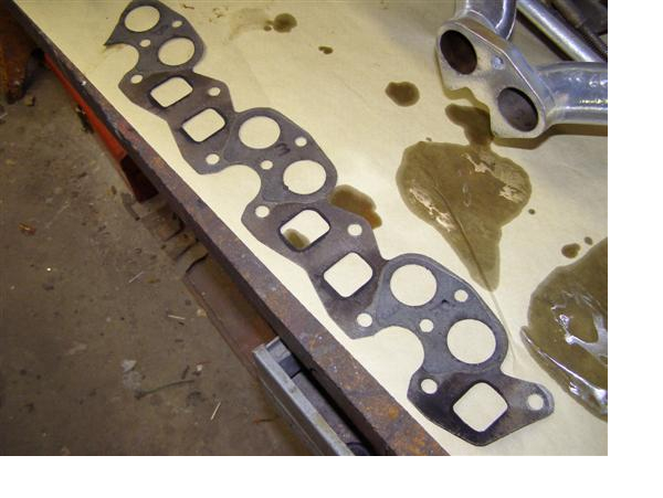
| Don, Berry, I chase all threads, internal and external, sometime several times, before committing a nut/bolt/screw. The Craftsman thread chasing set was one of the best investments I made in this adventure. Would recommend it to everyone contemplating an LBC restoration. Ordered new nuts from TRF. One came. It fit on the Cold Start Valve. The others are back ordered. Also ordered other external hardware from TRF. One screw seemed odd. It's too afix the By Pass Valve to the carburettor body. What I received was 5/32x3/8x16TPI. What i have on MY By pass valve is 5/32x3/8x32TPI!!! When challenged, Albert at TRF, Charles' number one son, opined that he had a carb on the bench in front of him and the screw was 16TPI. I know of no other fastener ANYWHERE on this LBC that takes a course thread at that diameter. In fact, there are damn few course thread ANYWHERE on the LBC. Anyone care to comment??? db |
| Doug Baker |
| Not the first to have a run in with him. Tell me what # in the book blow up and I will check mine |
| DON KELLY |
| Don, See response to your email. For others, apparently the 1970 carbs take a different screw for this application than do all the other years. And it's the By Pass Valve COVER to the By Pass Valve fastener that's of interest. db |
| Doug Baker |
Kind of rusty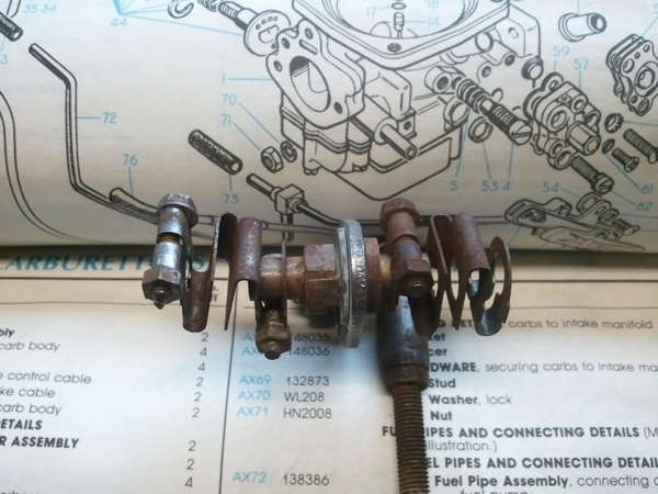 |
| DON KELLY |
| Don, Looks like you're missing one bolt and nut! TRF has these in stock. db |
| Doug Baker |
20 hours later
 |
| DON KELLY |
| Doug I guess I was asleep. Yes the Excell of trhe nuts and bolts is on the CD. However, have you added to it? If so I would like a copy to keep my CD up to date please. YA Don, looks like you are missing a nut and bolt on the left side. Rick |
| Rick Crawford |
| OOPPS Sorry....my other left DOH |
| Rick Crawford |
| That's because my nut and bolt guy can't count past 3 |
| DON KELLY |
| Geez Don - 20 hours later and your linkage is twice its original size! Tip from TRF Tech Line for anybody running a GP2 or similar cam and/or increasing compression by shaving the head. Engine/carbs now want to breathe differently. Tom at TRF says guys do everything right but ignore the simple carb jet. Brass Carb Jets, Moss part # 366-340 for reference are typically set(recessed) .125" below the carb body. TRF advised me to avoid continuous fiddling with the carbs and to get it right the first time, change the depth to .165". This should be done with a drift that has been machined to make contact only with the raised collar on the jet and not the seat in the middle where the metering needle makes contact, to avoid damaging the needle seat. If you think you can press a new one in to exactly .165" from the other side you won't need a drift. Good luck! Will let you know results if I ever get it all back together. Bob 1976 Disassembeled TR6 |
| Bob Evans |
| "Geez Don - 20 hours later and your linkage is twice its original size!" Soaking it in CLR will do that |
| DON KELLY |
| Bob, Please explain further. I shaved the head 0.020; the block, 0.010, bored the cylinders 0.020 over and installed a BPNW 270 cam, but I did NOTHING to the jet. What'd I miss? db |
| Doug Baker |
| "Geez Don - 20 hours later and your linkage is twice its original size!" You know, come to think of it. WISH MY WIFE WOULD SAY THAT  |
| DON KELLY |
| Hi Doug: IMHO you missed nothing but I called TRF Tech Help on a differential question and while I had Tom Spadafora on the line I asked him a bunch more questions and when I told him I shaved the head .060 thou he brought up the carb jet issue. He simply said I would get much better performance and a one-time, simple fix by setting the jet depth at .165" This is also closely connected to the upgraded cam and increased compression ratio issue. He also said I should have shaved the head another .040 thou to maximize compression ratio and used late GT6 pushrods, which are just the right length once the head is shaved. He said TRF does this on all the special order engines they build. I found him to be extremely helpful and keep in mind that as long as you are buying parts and paying the long-distance charges they will talk to you for as long as you want. Just get their Tech Line # from their website and ask to speak to Tom. I'm sure glad I did. Rumor has it that Charlie B. is roaming these parts so when I see him for a single malt I will show him this stuff and maybe he can provide his own input when he gets back to Ontario. In the meantime, call TRF. Cheers, Bob |
| Bob Evans |
| Don - you're mixing up your linkage with your Johnson. They're different part numbers! |
| Bob Evans |
| On the jet recommendation - you can get the same benefit by raising the fuel level in the float chamber a couple of mm. |
| Brent B |
| Do I dare click on IMAGE !!!!! |
| Rick Crawford |
| Bob, Brent, Talked to Tom Spadafora last night. Long conversation. He understands my setup and strongly suggests that I'm suboptimizing if I do not increase the fuel available. Again, a quick review...I shaved the block 0.010; milled the head 0.020, bored the cylinders 0.020 oversize all toward a 9:1 ratio (actually achieved a mite less). Balanced bottom end, new bearings, pistons, connectors, alloy flywheel and new head setup with SS/Stellite valves, hardened valve seats, double springs, bronze valve guides, mild polish to the intake and exhaust and rods to remove weight and even air flow. Had Distributer rebuilt and recurved for new BPNW 270 cam. New lifters, cam and crank gears and timing chain and new rocker arm rod. Tom opined that I should add electronic ignition and increase the fuel by lowering the fuel jet as you described Bob, but Brent, your idea seems simpler and should achieve the same end. Question is both of these modifications are variable. How do I determine the optimum fuel rate delivery and how do I get that with these hardware modifications given my setup? Trial and error? That'd be really laborious to take the carbs on and off, take apart, adjust, reinstall, test, then do it all over again, all for minor changes. There should be an analytical model/algorithem to get to a probable best setting then any fine tuning done with the adjustment screw on the jet and or bending the hinge on the float (I set the float at ther recommended 17mm initially). What'd y'all think? Any ideas? Thanks. db |
| Doug Baker |
| Go to SU's and change the jets? |
| DON KELLY |
| Hey Doug. I assume you're using dual Z-S carbs. Your set-up is not too different than mine. All you're trying to do is find a way to get the extra fuel into the cylinders while keeping the needles within the adjustment range of approx 3 turns. I found the 2 mm change worked fine (say 15mm instead of 17mm) in my application where the needles originally couldn't get the mix rich enough. Brent |
| Brent B |
| Another way to look at it: lowering the jet from 0.125" to 0.165" is a decrease in "head" of 1 mm. You get the same effect by raising the level in the float chamber 1mm. But, at a given needle position, lowering the jet also slightly increases the annular area for fuel flow. One can make assumptions and attempt to calculate the increased flow, but the other 1 mm in float chamber level increase seems to get pretty close to what's required. And you can always increase the level another mm if desired - that always struck me as more desirable than moving the jet. |
| Brent B |
| Brent, yes I have the original setup of dual ZS 175cd single barrel side draft carbs. Your approach makes good sense. Thanks. db |
| Doug Baker |
| Doug, best way to tell is either do dyno runs or install a logging system to check. |
| DON KELLY |
| Doug/Brent: I have very similar mods to yours and again I'm just passing on info I got from Tom Spadafora. As my TR is still on the jack stands I have not done the jet adjustments but I do like Brent's idea of changing the float level. It's much simpler and no chance of breaking anything. I think I'll try that first when I get everything back together. Hoping to begin the reassembly tomorrow with installing the diff complete with new side axle bearings and side and pinion oil seals. Have also had it drilled and tapped and installed the new magnetic drain plug. I had that done at the local machine shop. Hope to get some drives in before the summer passes me by. Cheers, Bob |
| Bob Evans |
| Finally got the throttle spring adjusted properly and have attacked the By-Pass Valve rebuild. Whoa!@! Anyone done this lately on 175CD ZS? The directions from Buckeye that I have been following show that the hexagonal cavity on the By-Pass Valve itself is open to the outside. Mine is not. How do I adjust the two piece valve and O ring inside this cavity? Must I remove the brass plug to effect proper adjustment? If so, with what do I replace it? Very confused. I've asked Tom at TRF, but I may have exhausted all credit with him by now. HELP. Thanks. db |
| Doug Baker |
| I just last week ,blocked mine off with a thin piece of aluminum. Not my pic 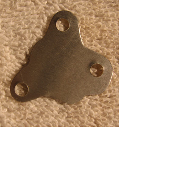 |
| Don Kelly |
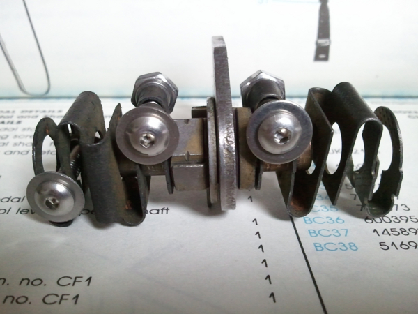
| Don, Here's what I'm talking about... See how the end is open? Mine's closed with a brass plug. What do I do to overhaul this...put it just like the one that's not yet dissassembled? Only option, I guess??!! db 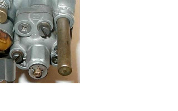 |
| Doug Baker |
| As you know Doug, Carbs are not my thing. That's why I blocked mine off . Did you read this if it helps http://www.vtr.org/maintain/zs-tech-tips.shtml Here is what mine look like 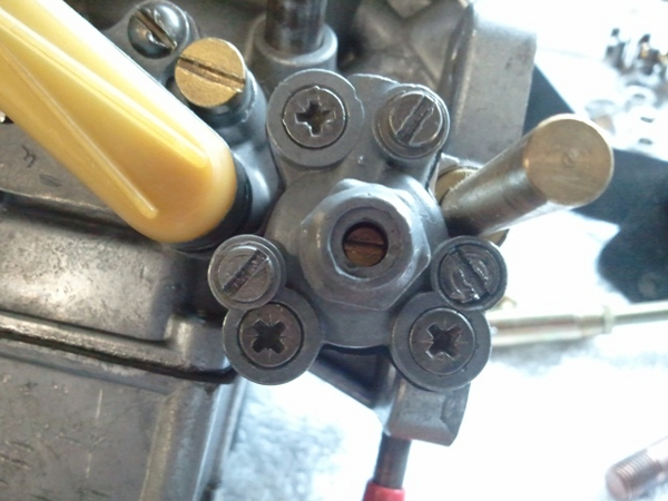 |
| Don Kelly |
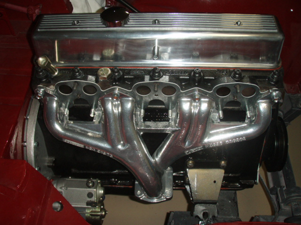
| And ,by the way, Those clamps for the manifolds are a pin in the keister if you are running the TT headers. I can't get one to fit and the nut hits the tube. Gonna try a 1 1/4 socket head screw |
| Don Kelly |
| Doug That little tamper proof plug can be removed and discarded. Make sure you replace the little o-ring on the inside that goes around the adjustment screw. I adjusted my BP valve by turning it completely CCW closed then 1/2 turn CW open. That seems to work best for me. I had it at 2 turns CW (there are appx 13 turns from full CW open to full CCW closed) and it was slow to return to idle. I may try the directions from the VTR link that Don ref. above. My TR is an early '71 Joe |
| Joe S |
| Joe. what the comm. # |
| Don Kelly |
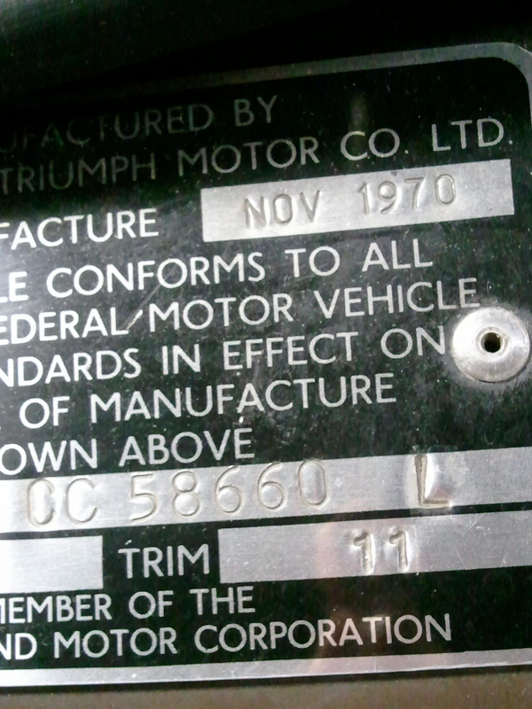
Would you believe CC60628LO Manufacture Date Dec.'70!!
 |
| Joe S |
| Joe, Thanks. I'm still mulling over an external adjustable valve vs a preset internal. I'm gonna look at the other carb and see what the adjustment is on it if I can from the inside out. Why are the anti-tamper plugs there if you're to remove them when you overhaul the carb? db |
| Doug Baker |
| Doug You might want to call Joe Curto (718-762-7878). He is the guy to go to for Zenith carb. answers. Removing the plug will make adjustment easier. |
| Joe S |
Joe, see that and raise yo a month
 |
| Don Kelly |
| Hate to say this boys, 90% done and I'm changing boats in the middle of the river. Dang it. Carb is on and the Ratco linkage was hooked up and the injectors ready to go in. Stay tuned for more 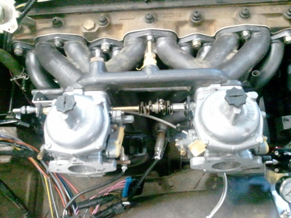 |
| Don Kelly |
| Don, Don, slow down. You're getting ahead of me again@!! What manifold is that. Looks a lot different than mine or your ceramic coated one!! You're missing a brass tag on your rear carb!! Nice looking carbs though. db |
| Doug Baker |
| That's a later manifold,it is ceramic coated, to go with my GT6 head. You want to buy this one from me? I know the tag is missing . You tried to pry that one from me years ago. 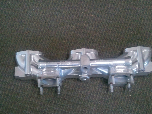 |
| Don Kelly |
| Don, this one still looks good, but it was better with the carbs attached!! After I turned my water connections out of the manifold and had to find one on Ebay, I'm not in the market for another...yet!! db |
| Doug Baker |
Speaking of ceramic jet coating... I scrapped the header idea and decided to go this route...
 |
| DWS Smith |
| Actually, in many circles they are considered superior |
| Don Kelly |
| DWS Very nice looking. I have the same valve cover. Have you made yourself a baffle for the air breather vent pipe? You will need to or you will slowly loose oil as it goes .....sorry gotta do this.....down the tube. Hey Doug, 2 more months and you will have kept this thread open for a year! Rick |
| Rick Crawford |
Re what rick said about the baffle. Your intake "could" look like this
 |
| Don Kelly |
Thanks for the compliment and the heads up on that. What have you used as a baffle? If you look at this pick you will see a plug in the blanking plate for the fuel pump. The plan was to eventually set up one of those Goodparts oil catch tank units with a return ine to the engine. I wasn't going to do this right out of the gate due to the cost. Being over budget on this project has me doing some sensible cut backs as I near the end.
 |
| DWS Smith |
| That is a great modification What's the deal below the dizzy pedestal? |
| Don Kelly |
| The brass plug is just to fill the hole upon initial start up. The sending unit will come later as the one I have is cracked. In case you are speaking of the cardboard and blue tape over the oil filter port... Just keepin the dust out... |
| DWS Smith |
| I made a baffle using thin 3003 aluminum sheet that was bonded with a high temperature adhesive and then solid riveted in place. It doesn't have to be much, it just has to make it harder for oil to splash into vent tube. See attached shot of the fitted baffle. I did add one of Richard's oil catch units and have it draining to the fuel pump block off plate, pretty straight forward stuff to fit it.  |
| SteveP1 |
| Steve, do those rivets show on the outside of the valve cover or are they pins that sit in dimples and are adhered to the aluminum? Are you pretty happy with the Goodparts kit? |
| DWS Smith |
Yes, the rivets show on the outside of the valve cover. It's been a while since it was done and I used rivets that were sitting around so don't recall the exact size or grip length but seem to recall that they were 5/32 and took a longer grip length and trimmed it back for a proper sized formed head inside the valve cover and left the button head on the outside. Rivets were installed with wet polysulfide sealant. If the memory on size is correct, that would make it an AN470-5-(something for the grip)A or MS20470-5-(something for the grip)A. The "A" indicates the material is 1100 series aluminum and for this I wanted a soft easily worked aluminum. Readily available from your local aircraft supply, places like Aircraft Spruce, etc. You could use something like an "AD" (2117-T4) or an "E" (7075 or 7050, oops, in a -T74 condition), but they are much harder to work with and you don't need the strength of those for this application.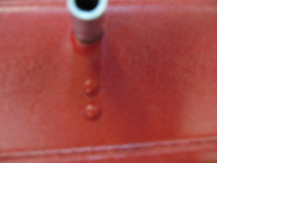 |
| SteveP1 |
| And for the other question: Richard's catch can/separator is essentially a welded up aluminum cylinder with slits cut into it and baffle plates inserted at an angle welded in to minimize what could get pulled back into the inlet tract and effectively force the oil to drain to the bottom plate. Overall, it's a nice piece but being the anal retentive sort, I couldn't leave well enough alone. I cleaned up the welds to a reasonable extent, shot it with black wrinkle paint and then changed out the plumbing hardware to AN fittings (I have an almost insane amount and variety of fittings sitting around that I picked up as surplus many years ago). I dispensed with the black hoses and bent up some tubing, beaded the ends on the one that runs from the valve cover over to the can, flared the ends on the other that runs from the fuel pump block off plate to a bracket. A flex line with Aeroquip fittings connected the flared hard line to the can. The can itself was mounted to the bulkhead using nutserts and washer, lock washer, 3/16 bolts. 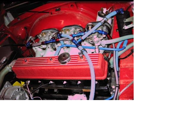 |
| SteveP1 |
| Steve... thanks for the detail...Nice tripples by the way... Rolling thunder I bet... |
| DWS Smith |
| Have asked this question else where. When I do my pump and I want to use AN fittings. Do I need a special tool to attach Aero hose to them? |
| Don Kelly |
| Don, It's not so much a matter of special tools as much as how is the pump configured and what adaptation needs to be done to make things work. |
| SteveP1 |
| Steve found a pic very similar to what I want to do. This would be hung behind the drivers wheel.  |
| Don Kelly |
| Don, Based on the picture and using these assumptions, here's what I'm seeing: The filter body is possibly set up with threads that match up to AN815-xD threaded unions. The pump body appears set to accept AN815-xD unions as well, but uses a smaller outlet size than inlet. Without knowing the details of the set up, this is speculative, best guess stuff. Between the two bodies are a couple of double female 90 degree elbows with another AN815-xD union. At least this part of it is pretty straight forward. Scaling things from the picture, best guess is the that "x" is a 6 for unions at both ends of the filter body, the pump inlet and between the two elbows. At the pump outlet, it looks to be a -4. Aeroquip part numbers for these would be: AN815-6D FCM2052 AN815-4D FCM2051 90 Degree -6 Female Swivel Flare Elbows FCM2978 As far as the balance of the stuff, it would boil down to how you wanted to set it up. To assemble hoses, something like their FCM3661 vise jaws are really handy in that they are cut to hold the components without damage. Aluminum wrenches are typically used with the alumnum fittings to protect the fittings, having two sets is nice as there are times when you need one for each hand. The down side is that the aluminum wrenches are easily damaged. Steel wrenches can be used, just have to be careful not to get ham fisted. Bottom line is that there are lots of components out there. You just need to know the details of your parts and select the appropriate ones for adaptation use. Even then you'll come across one and want/need to do something silly like boring out and machining the -5 end flare off the AN919-7D I used at the fuel tank outlet. |
| SteveP1 |
| Steve- The pump is a Walbro with a 10mm outlet,female. I haven't got the filter yet as I was waiting to see the pump first. Would it be better to space them out so a little hose is used between them? Just to isolate vibration? I was looking for the 90°'s in a male 10 mm but couldn't find that. Do they only come in female? |
| Don Kelly |
| Don, I looked up stuff from the Walbro external pump family, looks like they all have 10 x 1.0 inlet and outlets. The only metric adapter from Aeroquip in that thread is for a -4 AN flare under part number FCM2239. If we switch over to Russell, they have a better selection of metric to AN flare adapters. They have a 10 x 1.0 to -4 AN flare under part numbers 670500 and 670501 for blue anodized and their "Endura" finish although the 670501 shows to be discontinued with some stock available. They also show a 10 x 1.0 to -6 AN flare under part numbers 670480 and 670481 for the same respective finishes. Both sizes are straight fittings, I'm not aware of any 90 degree adapters for those sizes. Summit shows a Russell 670470 as being a 10 x 1.0 to -6AN flare, but a search on Russell under that number gives no results. Your guess is as good as mine on what is happening there. As for any metric to AN flare in a 90, not aware of any out there off hand although there might be some sort of Weber/Dellorto/Solex type out there with a 90, but they would be larger than 10mm. I'm not aware of any male-male swivel 90s out there, much less a metricated version (although there's a lot of bad joke potential in all of these statements). Russell makes some low profile AN flare swivels in both female-female and in mixed genders, but I don't like to use them unless I have to for packaging reasons. I prefer the nice gradual bends for better flow of the "normal" female-female swivels. As far as spacing them out so hose can be used, it would probably take up more real estate than you envision for that to be effective from an isolation standpoint or even just physical hose build up standpoint. As long as the components are rigidly mounted relative to each other and no undue stresses are placed on the 90 degree swivels, I'd go the flare adapter to swivel elbow to union to swivel elbow to flare adapter route between the pump and filter. |
| SteveP1 |
| Steve- most of the pump sellers have a 10mm to 6AN adapter for it. Another question Most of the people I have talk to says 3/8th to the regulator , what I don't understand is there are a lot of pumps with slip on 3/8's inlet and 5/16 outlets. In fact almost all are sold that way |
| Don Kelly |
| Don, That is just one of the reasons I offered up the speculation/best guess comment earlier as most do have beaded or barbed fittings at the inlet and outlet as oppossed to a threaded port and the outlet is smaller than the inlet. For the injection set ups the pressure is fairly high and you can get plenty of flow through 5/16 with those kind of pressures while the pressure is lower on the inlet side so the larger size helps to make sure the pump is fed. My guess on the primary reason for picking the 3/8 to the regulator is that -6 hardware is plentiful while -5 is sort of an odd ball size for most applications and there isn't nearly as much hardware available in that size. For the most part once you get above -3, you're looking at even dash sizes up to -16, then you typically start jumping up by four to -20, -24, etc. Going back to an earlier statement regarding 90 degree metric to AN flare swivels, I didn't think to look at Earl's at the time I responded earlier. I went back and looked and they do have both male and female 90 swivel -6 AN flares to metric, but not in a size that helps you out. It's 12 x 1.25 and 12 x 1.5 threads only. Need to keep that in mind though for future reference. Just keep that AN919-7D reducing union number handy as that is your path to -6 sizing out of the tank. Remove the flare from the -5 side of the reducer by machining/grinding (smooth down any rough surface if you grind) then bore it out to 3/8 and alodine the exposed surfaces where the flare was removed and the bore opened up. Intall it to the tank outlet with a sealing washer and you're now set up for -6 right out of the tank. |
| SteveP1 |
| Well do you think that the 5/16's is suitable for the line to the reg than. I have been waiting to purchase and install until the pump is in. Both Patton and the guy selling the ITB's say 3/8's |
| Don Kelly |
| My personal opinion is that 5/16 would be sufficient. The rationale behind that position is that the stock TR-6 fuel system uses 5/16 with a mechanical pump and that gets plenty of fuel through the system to feed the Strombergs and I've even known people to run that with triple DCOEs and keep them fed under all but the most extreme conditions. If you're going to run so much more fuel through a TBI set up that 5/16 can't feed it, then I'd question the logic of the system. If you had somehow managed to make an absolutely fire breathing TR-6, then I'd have an easier time buying into it, but would still have wonder. I just don't see a TR-6 motor ever being capable of breathing that much fire and not being a short fused grenade. I don't know anything about the regulator mentioned so perhaps something related to it is why Patton and the ITB guy are saying 3/8. What I can tell you is that if you plan on using AN flare type hardware and Aeroquip type hose and fittings as in the illustration, just go with the -6 as there's not enough readily available -5 stuff out there to build up the system. You'd be looking at lots of special orders and fabrication if you really wanted to go -5. |
| SteveP1 |
| Steve- Are Banjo bolts for fuel different than brakes? |
| Don Kelly |
| The answer is
..it depends. Most hydralic system items are -3 or -4, while fuel system items are typically larger in diameter but there are some exceptions out there. Banjo bolts are banjo bolts and they dont really care what type of system is being plumbed. What matters is selecting the appropriate set up for the application. Taking fuel systems for example, the banjo bolts used for attaching the fuel lines to the DCOEs in the attached picture above are aluminum with dead soft 1100 series aluminum crush washers. The rationale is one of metal compatibility and applied loads. If instead it was higher loads and pressures along with different body materials, then use of steel or brass banjo bolts and fittings might be in order. While I have seen aluminum plumbing used on brake systems, steel is more common because of the higher loads and potential for higher temperatures. But again, we come back to a banjo bolt being a banjo bolt and not caring what it is used for as long as it is appropriate for the application. |
| SteveP1 |
| Was thinking using that instead of the Russell and Aero stuff |
| Don Kelly |
This thread was discussed between 06/01/2011 and 29/11/2011
Triumph TR6 index